

- Stock: 10
- Model: 1005002649326100
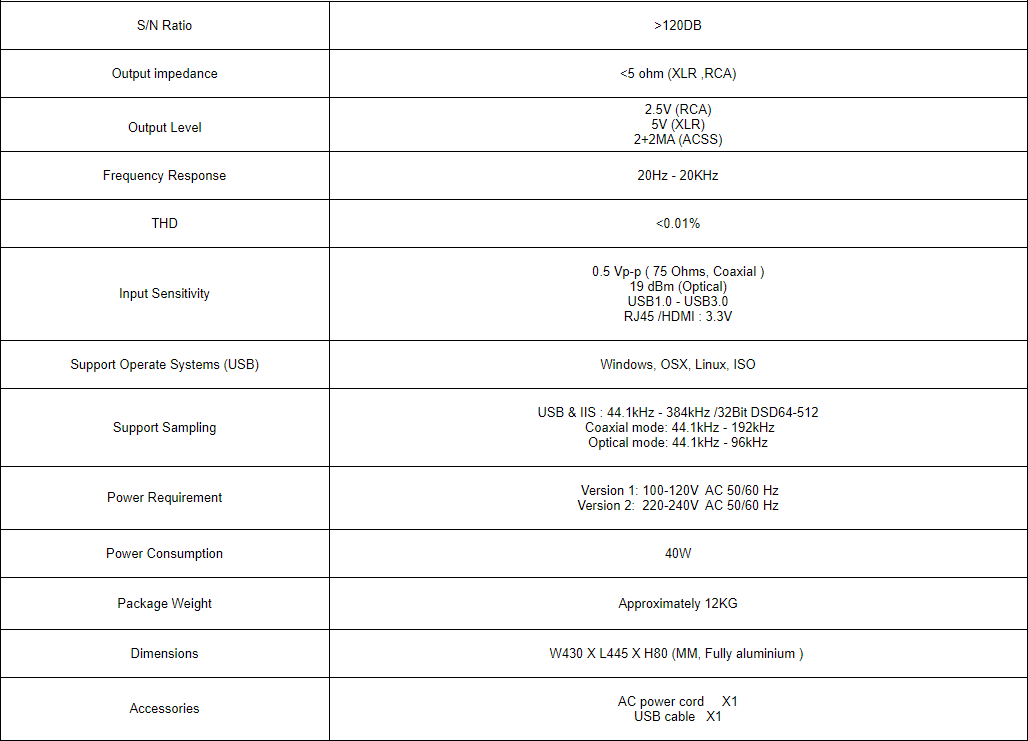
- Weight: 12.00kg
- Dimensions: 50.00cm x 50.00cm x 13.00cm
- SKU: 1005002649326100
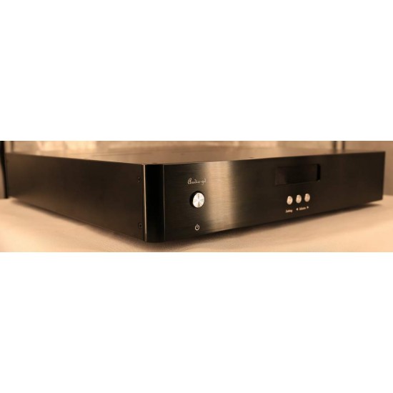
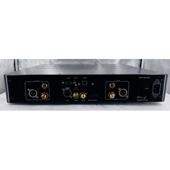
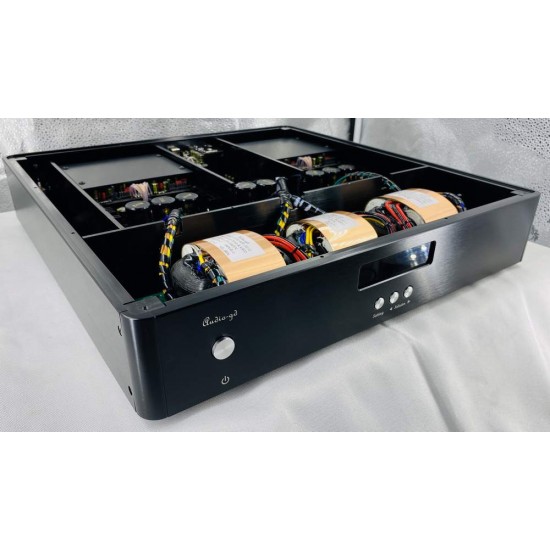
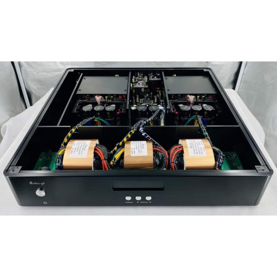
Audio-GD R-8 MK2 True balanced fully discrete DAC
Features of the R-8 MK2:
1. Fully discrete true balanced current transfer design.
4 fully discrete individual DSD hardware decoders,
8 fully discrete R-2R DA modules forming a two-channel balanced push-pull decoder.
A newly designed discrete servo-regulated power supply is used to supply power exclusively to the digital circuitry, offering performance comparable to that of a battery but avoiding the dry sound characteristics of battery power, and allowing the product to operate at much lower temperatures than older models. The clock and analogue circuits are still powered by a pure Class A regulated power supply for optimum sound matching. (New upgrade)
2. After listening to the vinyl system for a long time, we have managed to incorporate the analogue vinyl sound characteristics into this product, by controlling the inclusion of the analogue function with the push of a button. (New upgrade)
3, USB and HDMI inputs are equipped with separate isolators and two linear power supplies to separate the USB and HDMI power supplies in front of the isolator to eliminate interference from the signal source.
a, USB uses bi-directional transmission isolators, both transmitting IIS signals to the FPGA processor and receiving synchronous clock signals from the FPGA processor, the USB interface itself is no longer equipped with a data clock, using synchronous clock to make the signal transmission more accurate, so that the sound quality is greatly improved to better than the previous generation R-8 plus DI-20 (but not DI-20HE).
b, HDMI is equipped with a separate isolator to improve the sound quality of the HDMI input.
4, Display of input signal sample rate function. (New upgrade)
5, The entire digital circuitry is composed of one FPGA and five CPLD programmable devices, allowing the different functional circuits to be separated to isolate interference, applying the fastest parallel data processing mode, and supporting firmware upgrades to improve the sound quality.
The FPGA data processing mode is parallel.
The IIS signal is a serial data mode, each data requires one clock cycle, one frame of left and right channel data requires 64 clock cycles and is affected by the stability of 64 clock cycles.
The parallel mode requires only one clock to transmit and process the 32-bit data of the left and right channels, which greatly increases the operating speed and is less affected by the stability of the clock.
The IIS input data (USB and HDMI-IIS) is immediately reassembled into two sets of 32-bit parallel data as soon as it is input, and the SPDIF signal is demodulated and sent to the next level of processing in two sets of 24-bit parallel data, while the DSD data is also reassembled into two sets of 64-bit parallel data as soon as it is input.
The parallel processing mode results in a clearer and more neutral sound with better dynamics and a more analogue flavour when compared to listening.
6, Two Accusilicon clocks up to 90/98MHz provide synchronised clocking throughout the unit for high bit rate music playback without the need for PLL upscaling.
The new architecture of the clock management design allows for more stable clock operation and greater transparency and detail.
7. The DSD uses a built-in asynchronous clock to re-calibrate, significantly improving the clarity and dynamics of playback.
8, SPDIF supports DOP playback.
9, All digital mode settings can be done on the panel (no need to open the machine).
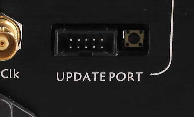
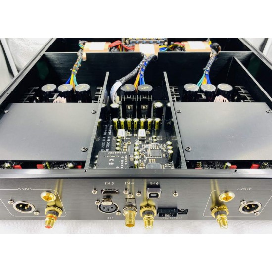
10. Firmware upgrade port installed on the rear panel (no need to open the machine to upgrade the firmware).
Manufacturers in the Hi-End market use quite sophisticated techniques to solve the problems of the R-2R in order to achieve high performance and sound quality. Some manufacturers use the serial control mode of the shift register IC.
The design shown below uses an FPGA to control the ladder resistor switch in parallel. In parallel control mode, each bit of the ladder resistor switch is controlled individually and therefore has a very high speed (parallel mode requires only 1 clock cycle to send or update all data, whereas serial mode requires at least 8 to 24 clock cycles) to send or update data and can correct the data instantly at any time, resulting in a low distortion output signal and solving problems caused by resistor tolerance and Glitch, etc.
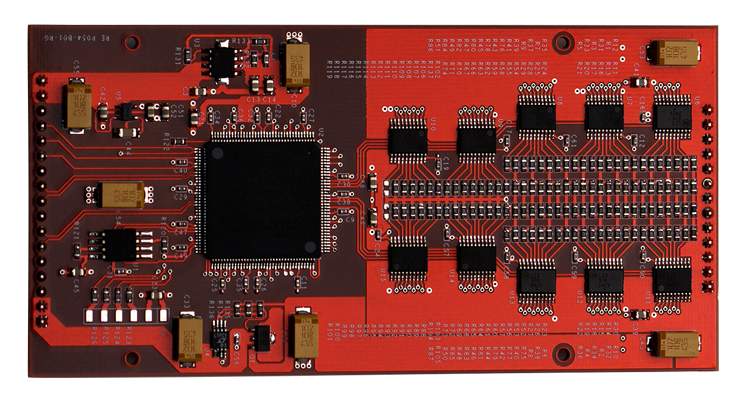
Considerable importance of FPGAs/CPLDs:
FPGAs/CPLDs are programmable logic array devices.
Today, FPGAs are used in a number of Hi-End level DACs, such as the popular
ROCKNA WAVEDREAM DAC:
We have been using FPGA designs in DAC products since 2008.
The machine consists of one FPGA and five CPLD chips to form the entire digital circuit.
The hardware layout inside the FPGA can be designed and arranged by software, and the hardware can be upgraded by software updates.
When the firmware is upgraded, the hardware is upgraded at the same time. This provides a high degree of flexibility, allowing software upgrades to improve sound quality, add newer features, and keep the product always up to date.
The FPGA/CPLD with great responsibility:
1. High performance SPDIF demodulator built into the FPGA instead of the low performance SPDIF demodulator chips such as DIR9001, WM8805 and AK411X which are cured in the market.
2, Restructured clock and FIFO technology, output data can be accurately synchronized to the clock, rejecting jitter.
3, Built-in 2X, 4X and 8X digital filters and different algorithmic NOS modes for users to choose the most suitable tone for their personal taste.
4. The unique design simulates the sound of a vinyl playback system.
Fully discrete output stage:
The last stage through which the signal passes is the analogue output stage, which has a decisive influence on the sound quality of the DAC. The best digital circuit design without a good analogue output stage design will result in extremely mediocre sound quality.
The high-speed CAST amplifier acts as the signal amplifier and processor. The CAST amplifier is designed without negative feedback and operates in current signal mode, rather than having to repeatedly shift the signal between current and voltage as other designs do.
The output buffer stage is a single-ended pure class A FET design and two sets are connected in parallel to achieve a lower output impedance.
In short, the output stage operates in a pure Class A state, with no negative feedback at all, in order to reproduce a pure and realistic sound signal.
The DAC has four OPA op-amps built in to act as DC servos, so that the DAC can operate without coupling capacitors, avoiding the sound taint caused by capacitors.
No switching components are used in any of the signal channels after the DA module to achieve the purest and most realistic sound quality.
Powerful power supply design:
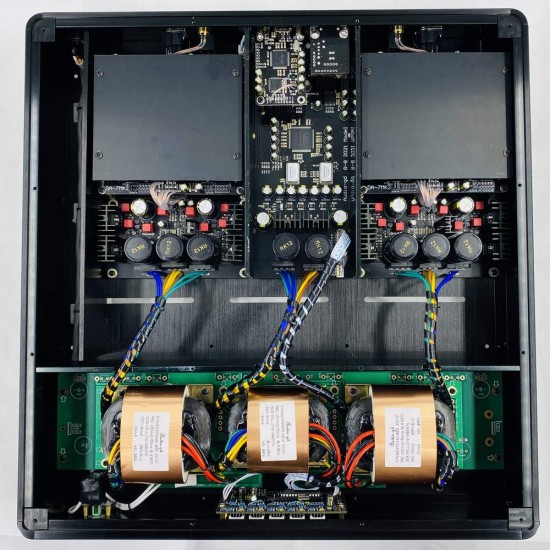
The DAC has three built-in R-transformers with a total power of 135W, supplying the digital section and the analogue sections of the left and right channels separately and independently.
The digital processing circuitry is powered by nine ultra-high speed, low-noise regulated power supplies, which are doubly regulated.
The analogue section uses four pure Class A regulated power supplies for the output amplifiers and four discrete servo-type regulated power supplies with battery-like performance for the DA module.
All power supplies are ultra-high speed and ultra-low noise. The pure, independent power supplies provide optimum performance and sound quality for each part of the circuit.
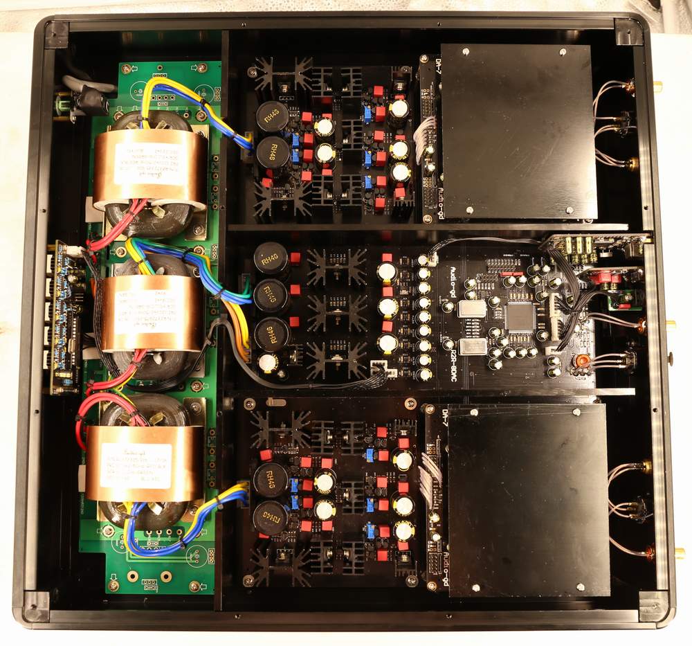
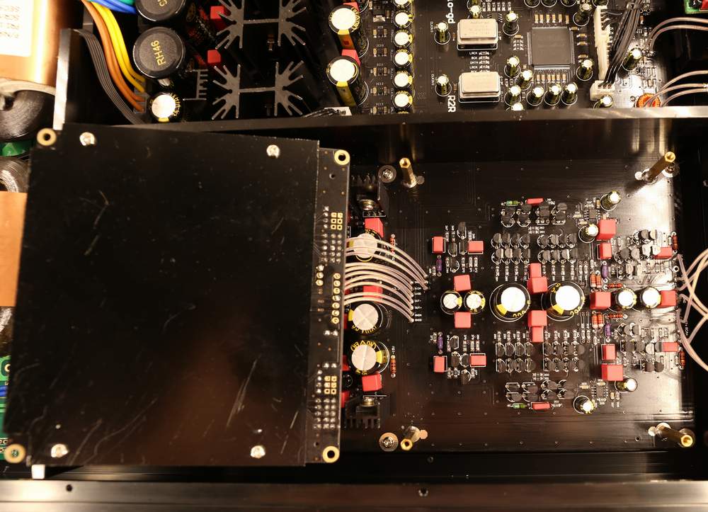
Layout :
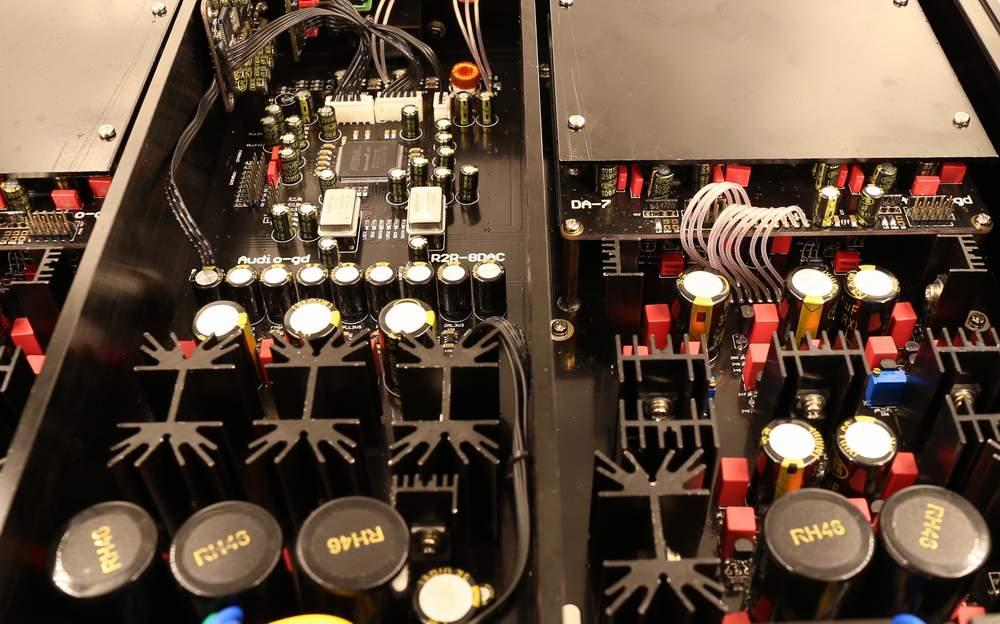
The DAC uses a 5MM thick aluminium plate to separate the digital section, the left and right channel analogue sections and the transformer section to avoid interference between them.
The analogue sections of the left and right channels are laid out symmetrically on both sides of the digital section, with the same length and distance between the signal lines, resulting in more accurate sound quality.
The elaborate layout and installation process only results in a clearer and more pure sound quality, a more peaceful background and a wider soundstage.
 Notes on purchase and use:
This product uses the latest power supply technology, which reduces the temperature more than the previous generation of products, and can be turned on for a long time.
Even though the product will only be delivered after 100 hours of ageing, we recommend that users age it for an additional 300 hours and connect it to a signal source to play music during ageing.
The quickest way to complete the ageing process is to connect to a signal source and play music for 15 days. (The amplifier can be switched off if you do not want to listen to music)
This product is simple to use and the user guide is published on this website only and is not provided separately.
To connect or disconnect the input and output cables, please do so with the power off.
Each time the amplifier is switched on, there must be a minimum of 30 seconds between the last time it was switched off.
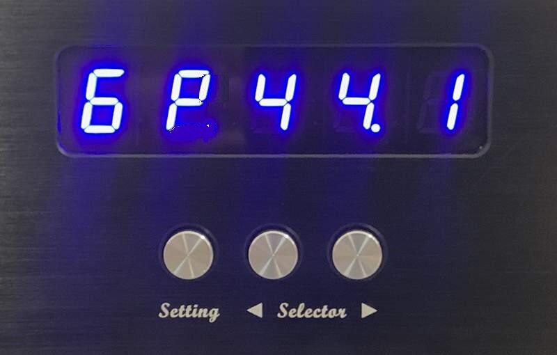
In normal operation the following is displayed:
First display: input channels include 1, 2, 3, 4, 5, 6 (see description below for details).
Second display: input signal format display, P in PCM format, d in DSD format.
The third to fifth display: the input sample rate, including 44.1, 48.0, 88.2, 96.0, 176, 192, 352, 384 is indicative of the PCM sample rate, while 064, 128, 256, 512 is indicative of the DSD sample rate.
 Function setting guide:
Page 1 Menu :
Left 1 Display bit (Oversampling technology) :
"O" selects Oversampling (OS), "N" selects No Oversampling (NOS).
Left 2 display bits (OS and NOS modes):
When OS is set to "O" the DAC is operating in Oversampling mode, the lower number OS Mode makes the sound thicker and softer. Depending on your sound preference.
Mode "0" : NOS mode for conventional technology.
Mode "2" : 2X oversampling.
Mode "4" : 4X oversampling .
Mode "8" : 8X oversampling.
When the OS is set to "N" the DAC is operating in NOS mode, the NOS mode is upgraded to the new architecture configuration so that the display shows 1-3, all resulting in only one NOS mode.
Display bit 3 left (Simulate vinyl system tone).
S (Simulate) : Activates the DAC to emulate the sound of the vinyl system. It is recommended to set to OS0 or NOS mode for use.
n (Non-simulate) : Does not use the emulation function.
Left 4 display (alternate future upgrade function, no function now) :
Left 5 display (alternate future upgrade function, no function now) :
Page 2 Menu :
Left 1 display bit (Display display function) :
Activate (1) the display auto switch-off function, the display will automatically switch off approximately 10 seconds after stopping any key operation. Deactivate (0) the automatic display switch-off function, the display will remain on.
Setting demonstration:
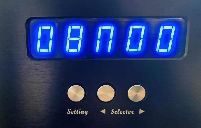
1, set to the most neutral sounding mode (8x oversampling, not emulating vinyl mode)
Press the "SETTING" button, the first display bit flashes, set to "O" with the "RIGHT INPUT" button.
Press the "SETTING" button again, the second display bit flashes and is set to "8" using the "RIGHT INPUT" button.
Press the "SETTING" button again, the third display bit flashes and is set to "n" using the "RIGHT INPUT" button.
 HDMI definitions : (PS audio format compatible):
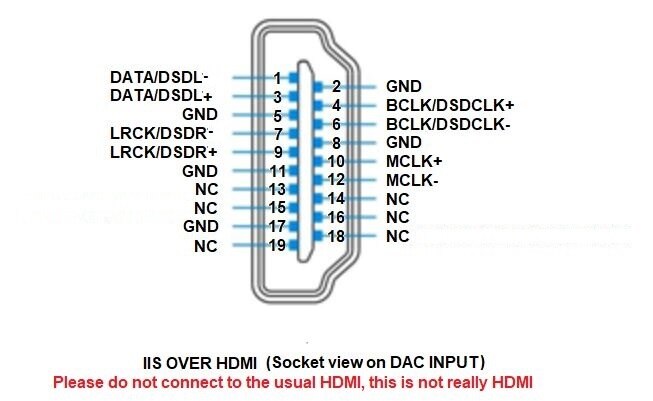
The MLCK signal is not required for this unit, but will not be affected even if the signal source has an MLCK output.
Firmware upgrade guide:
An upgrade port is available on the rear panel of the product, allowing users to connect and upgrade the FPGA firmware and Amanero firmware without having to open the machine to do so.